Using an electric current to deflect a magnetised needle gave rise to the Electric Telegraph. Railways were one of the first users of the electric telegraph to allow communication over long distances.
The Single Needle Telegraph was based around two Polarised Galvanometers connected in series, one at the sending end, one at the receiving end. In a polarised galvanometer, an electric current flowing through a coil under the influence of a permanent magnet causes the movement of an armature carrying a pointer. Current in one direction deflects the pointer to the left, current in the opposite direction deflects the pointer to the right. The current is produced by two batteries, connected to the galvanometers by operating one of two switches. One wire is needed from the sending end to the receiving end, plus a return which can be the Earth (or, in the case of a railway, one of the rails).
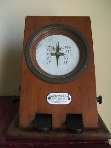
A Single Needle Telegraph Instrument from which Signalling Block Instruments were derived.
This idea was then adapted to give two adjacent signalmen an indication as to whether the line between them was occupied by a train or not. Provided the controlling signalman operated the switches correctly, the method worked well and the Block Signalling System remains in use today. There's an article describing one type of Block Signalling Instrument here.
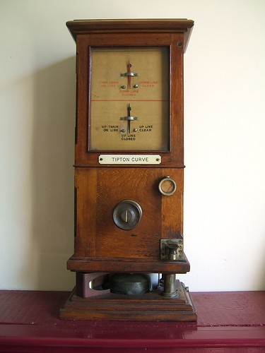
L&NWR type 'DN' Absolute Block Instrument.
Another application for Polarised Galvanometers was to confirm to a signalman the state of a semaphore signal which was out of sight, by fixing electric contacts to the signal arm to pass a current of one polarity if the arm was 'on', or opposite polarity if the arm was 'off'. Any position in between 'on' and 'off' passed no current, so that the signalman knew there was a problem. A similar technique was used to prove that the signal lamp was lit. There's an article here.
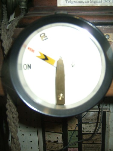
A polarised galvanometer arranged as a signal repeater for an upper quadrant semaphore distant signal.
The electro-mechanical Relay (often just called a 'Relay') is widely used in control systems in many forms. There's a useful introduction in Wikipedia here. A relay comprises a Coil and a pivoted Armature carrying one or more electrical Contacts. An electric current passed through the Coil produces an electromagnetic field which attracts the Armature. The movement of the Armature operates the Contacts which switch controlled circuits.
By using an electro-mechanical Relay to detect an electric current flowing through the rails, a method of detecting the presence of a train, called a Track Circuit, was developed and perfected in America. To provide the necessary safety, a d.c. current is circulated through the rails to operate a relay when there is no train present. When a train is present, the metal wheels and axle of a train 'shunt' part of this current, so that the relay releases and contacts on the relay can indicate that the track is occupied. Failure of the power supply or wiring cause the relay to release, indicating that the track is occupied, even if there is no train present. This type of design is called 'Fail Safe' and is a fundamental principle of railway signalling.
The relay itself must be highly reliable so that it cannot give a false 'Clear' indication, for instance, if contacts become 'welded'. Consequently, railway signalling relays tend to be more elaborate than relays used for less vital tasks. In this country, a common form of railway signalling relay was the 'Shelf Relay' with vertical Coils above a glass-sided chamber mounting the pivoted Armature and the Contacts, as shown in the picture below. The picture shows a Shelf Relay for use in d.c. track circuits. It has a 9 ohm coil resistance and operates two 'Front' (normally open) and two 'Back' (normally closed) contacts. The rather odd terms used are because, on most designs, the terminals nearest the maintainer when mounted on a shelf (those at the front) connect to normally open contacts whilst those behind (at the back) connect to normally closed contacts. However, the design of the illustrated relay puts the 'Front' contacts at the back, but the terminals are clearly marked 'F' and 'B'.
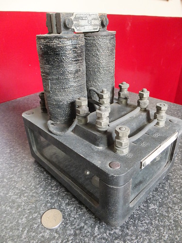
Neutral Track Relay ('Shelf' type).
Each relay carried a paper test label signed and dated by the tester recording the performance of the relay. Relays were usually 're-certified' every ten years. The two critical parameters for the above relay are recorded on the re-test label:-
Min P.U. 1.47 voltsThe first (Minimum Pick Up) guarantees that the relay will not 'Pick Up' (operate) until at least 1.47 volts is applied to the coil, guaranteeing that spurious voltages will not operate the relay.
Max D.A. 0.239 volts
The second (Maximum Drop Away) guarantees that below 0.239 volts applied to the coil, the contacts will have 'Dropped Away' (released), proving that the contacts are not 'sticking'.
The introduction of track circuits gave rise to the need to mount relays in signal boxes or at the lineside and this was often done by providing a wooden cupboard with one or more shelves on which 'Shelf' relays sat. The picture below shows a number of Shelf Relays wired as necessary.
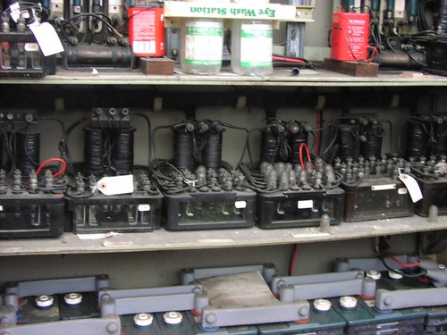 An elderly installation of shelf relays at Waterloo, prior to de-commissioning.
Simple relays, as described above, will operate the contacts whichever way the current flows through the coil. They were said to be 'neutral'. Some applications require a relay which is polarity-sensitive. This is achieved by incorporating a permanent magnet in the design so that the Armature only moves, operating the electric contacts, on one polarity of current. Current of the opposite polarity produces no movement. This type of relay has many applications in signalling control - for instance, 'proving' that a Block Instrument is displaying 'Line Clear' before allowing the signalman to release an electric lock on a signal lever.
 Style 'J' Polarised relay by Westinghouse Brake & Signal Co. Ltd.
This relay has two coils, each with 15,200 turns of insulated copper wire giving an electrical resistance of 500 ohms. The two coils are then wired in series, giving an overall coil resistance of 1000 ohms.
Everything is assembled onto the 'top plate' of bakelite (or similar). All external connections are made by connecting wires to the bolt-type terminals fixed to the 'top plate'.
The lower part of the case appears to be cast aluminium. In addition to the Westinghouse label screwed to the top plate, note the British Rail paper test label signed and dated by the tester recording the performance of the relay. The two critical parameters are recorded:-
Min P.U. .0055 Amps
Max D.A. .0033 Amps
The first (Minimum Pick Up) guarantees that the relay will not 'Pick Up' (operate) until 5.5 milliamps are flowing in the coil, guaranteeing that spurious currents will not operate the relay.
The second (Maximum Drop Away) guarantees that below 3.3 milliamps through the coil, the contacts will have 'Dropped Away' (released), proving that the contacts are not 'sticking'.
There are many other designs of relay for particular applications and many types of track circuit beyond the simple d.c. pattern.
In general, 'Shelf Relays' have been replaced by more modern designs but similar 'fail-safe' principles are incorporated. The 'BR930' is the generic reference for a range of more modern miniaturised plug-in relays still widely used on British and some overseas railways. These are widely known as 'Q' relays as this was the Westinghouse reference. A typical relay is illustrated below.
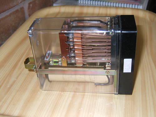 BR930 plug-in signalling relay made by Mors Smitt UK Ltd.
Even on modern relays, such as the 'BR930' plug-in relay, contacts are still referred to as 'Front' (or 'F') and 'Back' (or 'B'). The reduced relay size allows complex schemes to be assembled using large numbers of relays, as illustrated below.
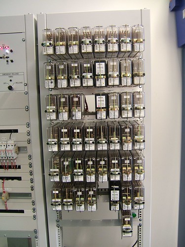
Relay control system on London Underground used for training purposes.
Overseas, different modern relay designs have emerged but intended to provide the same high integrity as British relays. As an example, the picture below shows an installation in Ukraine using Russian designed equipment.
 Signalling relay room, Mikulichin, Ukraine.
In the last few decades, railway signalling has undergone a revolution. The use of electronics is now widespread and Solid State Interlocking (SSI) is widely adopted and extensive areas are controlled from just a few signalling centres. This development has required the use of complex techniques to emulate the 'fail safe' properties of earlier systems. Except on lightly-used lines mechanical signalling is being eliminated.
 Solid State Interlocking equipment in a London Underground signalling training school.
Books
There are many, many books available on railway signalling. Here's a selection of some, generally older, books I've found interesting which include descriptions of the use of electricity in railway signalling:-
[ 1] ‘Power Railway Signalling’ by H. Raynar Wilson published 1908. (available from various sources as a reprint).Related posts on this website
[ 2] ‘The Style L Power Frame’ written and published by J. D. Francis 1989 (ISBN 0 9514636 0 8).
[ 3] ‘Railway Signalling and Communications: Installation and Maintenance’ based on lectures to LNER staff in 1946. Reprinted Peter Kay ISBN 1 899890 24 6.
[ 4] ‘Fifty Years of Railway Signalling’ by O. S. Nock (Institution of Railway Signal Engineers) covering 1912-1962.
[ 5] ‘Two Centuries of Railway Signalling’ by Geoffrey Kitchenside/Alan Williams (Oxford Publishing Co.) ISBN 0 86093 541 8.
[ 6] ‘Railway Signalling: A treatise on the recent practice of British Railways’ edited by O. S. Nock (Adam & Charles Black, 1980) ISBN 0 7136 2067 6.
[ 7] ‘Railway Control Systems’ edited by Maurice Leach (A & C Black 1991) ISBN 0-7136-3420-0.
[ 8] ‘Single Line Control (British Practice’) by P. C. Doswell (Booklet 4, Institution of Railway Signal Engineers 1957).
[ 9] ‘Multiple Aspect Signalling (British Practice)’ by A. Cardani (Booklet 14, Institution of Railway Signal Engineers 1958).
[10] ‘Route Control Systems AEI-GRS’ by A. C. Wesley (Booklet 21, Institution of Railway Signal Engineers 1961).
[11] ‘Route Control Systems:- The S.G.E. 1958 Route Relay Interlocking System’ by J. V. Goldsbrough (Booklet 22, Institution of Railway Signal Engineers 1961).
[12] ‘Level Crossing Protection’ by P. A. Langley (Booklet 25, Institution of Railway Signal Engineers 1961).
There's an incomplete series of posts titled 'Railway Signalling in Britain', starting here, with links to subsequent posts.
There's an incomplete series of posts titled 'Spring Vale Electrical Controls', starting here, with links to subsequent posts.
There's yet another incomplete series of posts titled 'Princes End Electrical Controls', starting here, with links to subsequent posts.
There's a brief post here describing Russian-style all-electric signalling at Mikulichin, Ukraine.
Alternately, you can find all my posts on Railway Signalling (mechanical and electrical) here.
My pictures
British Railway Signalling Equipment.
Signalling at Mikulichin, Ukraine.
