The 'Rocket' (built 1829) is the locomotive which everyone has heard of but the 'Planet' class, which followed less than a year later, represented a significant maturing of the principles first brought together in the winner of the Rainhill Trials.
On 2nd October 1992 the Museum of Science and Industry in Manchester brought into service its 'Planet' replica, at an official launch by the Lord Mayor of Manchester, Councillor William Egerton.
 'Planet' with M.S.& L. 'Tri-composite' and replica 1830 coach after the official launch (Picture: Steam Railway News).
A number of private steamings for the Sponsor, British Engine Insurance, followed. The 'Planet' replica entered public revenue service for the 'Railway Weekend' on 31st October and 1st November 1992.
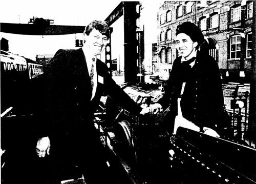 The 'Planet' replica during a private steaming for the Sponsor, British Engine Insurance, October 1992. On the left, the Public Relations Manager for British Engine Insurance, on the right, Jan Ford.
To celebrate the achievement, the January 1993 edition of 'Lionsheart' [see Note 2] included the article "Planet Steams Again" under the nom-de-plume '41901'. This post is based on that article, with minor changes to accommodate placing on the Internet.
"Planet Steams Again"
Dr. Richard Hills, former curator at Liverpool Road Station, Manchester is quoted in the July 1984 'Railway World', when talking about the building of replica 1830 coaches, as adding "One day, if finances allow, the dream might be realised of building a replica locomotive of the same period to go with the coaches".
The Liverpool Road site has now become the Museum of Science and Industry in Manchester - one of Europe's premier science museums - and, with the assistance of the Museum Friends, British Engine Insurance and others, that dream has now been realised.
The direct descendant of 'Rocket' was the 'Northumbrian', illustrated in the Shaw print below [see Note 1].
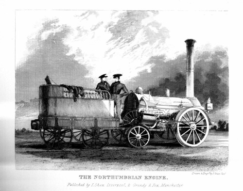 Shaw: Plate IV The Northumbrian Engine.
But the Shaw print of 'Planet' below [see Note 1] shows the new direction upon which locomotive design embarked.
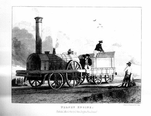 Shaw: Plate VIII Planet Engine.
The single driving axle was retained (and this remained a feature of fast, free-running engines for many years) but the outside cylinders were moved inside. The position of the cylinders was also moved from the rear of the locomotive to the front, so the 0-2-2 wheel arrangement of 'Rocket' and 'Northumbrian' became 2-2-0 in 'Planet' Probably the strongest motive for this change was the increased efficiency possible through enclosing the cylinders within the smokebox, enabling the cylinders to be kept warm. A consequence of the inside cylinders was the need for a cranked driving axle and, with 1830s technology, this presented serious manufacturing problems. Broken crank axles plagued railways for years to come.
The crank axle on 'Planet' was provided with inside bearings but, for the first time, a substantial wooden frame appeared, allowing the use of outside bearings as well on the driving axle.
Care is necessary when studying early reports and illustrations. Many misunderstandings arose, particularly when artists who were unfamiliar with railway equipment attempted to represent these novel inventions. The attractive, but perhaps imaginative view of 'Planet' reproduced below forms the frontispiece to the second edition of 'A Practical Treatise on Railroads' by Nicholas Wood, published in 1832. However, in another context, Zerah Colburn sharply comments, in his own work 'Locomotive Engineering and the Mechanism of Railways', "It is of course possible too, as was the case with nearly all the illustrations of Mr. Wood's book that ...(it)... was not accurately drawn".
 'Planet' from the frontispiece to the second edition of 'A Practical Treatise on Railroads' by Nicholas Wood, published in 1832.
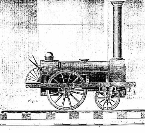
The undated lithograph of 'Planet' below gives a good overall impression of 'Planet'. In this diagram, 'Planet' has a splasher displaying the locomotive name.
 'Planet' from an undated lithograph of published by Geo. Smith, Liverpool, now in the Liverpool Public Library.
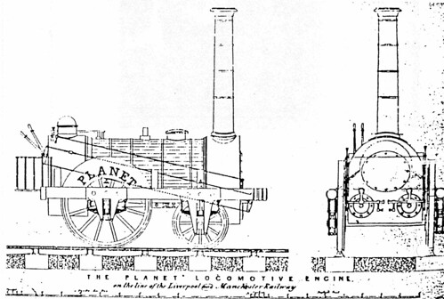
The splasher is also shown in the contemporary lithograph below (which appears in 'The British Railway Locomotive 1803 - 1853, published by the Science Museum).
 Stephenson's 'Planet' 2-2-0 i.c. locomotive, Liverpool and Manchester Railway, 1830. From a contemporary lithograph by H. Austen.
I believe that the model of 'Planet' at the Science Museum also features the splasher, although they are not shown on the drawing below which purports to show the Science Museum model. With part sectional views, there's plenty of constructional detail to be studied.
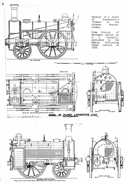 Details of a model of Stephenson's 'Planet' in the Science Museum, London. From 'History of Railways', edited by E. L. Cornwell, published by the Hamlyn Publishing Group Limited in 1976.
In general, other sources do not show 'Planet' with splashers. It has to be understood that locomotives of this period could vary in appearance during their lifetime. When a locomotive went in for 'shopping', it was taken down to its constituent parts, many of which might be replaced. Different ideas might be tried out, changing the appearance of the locomotive. Only partial records remain of all this work and it is difficult to be certain of the detailed history of locomotives of the period. This is certainly the case with 'Lion', first built in 1838. Debate still exists about the age of the various parts!
The diagram below is from Zerah Colburn's book [Reference 4]. This shows one of the later 'Planet' class locomotives built by Fenton, Murray and Jackson in 1834. The 'Planet' replica at the Museum of Science and Industry is quite similar, but there are detail differences.
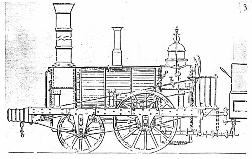 Passenger locomotive by Fenton, Murray and Jackson, 1834. General type of the 'Planet' class.
Below is another Shaw print [see Note 1] depicting 'Planet' passing the famous Skew Bridge at Rainhill.
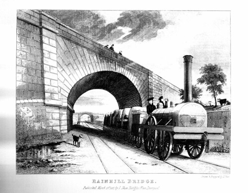 Shaw: Plate VII Rainhill Bridge.
One curious detail on both of Shaw's 'Planet' views is the small, hinged door on the smokebox front. Artistic license? Certainly, with about 12 bolts securing what is quite a heavy smokebox front, regular removal of smokebox char is hardly encouraged!
J.G.H. Warren's book [Reference 2] has some fascinating details of the design of 'Planet'. With his access to the manufacturer's records, these are probably the most accurate source we have and three pages of diagrams taken from Warren's work follow.
Page marked '16': This has overall views and sections. The original 'Planet' boiler was very satisfactory and the construction is made clear in the diagrams which were derived from the earlier publication 'Treatise on Locomotive Engines' by De Pambour published in 1836. The 'Planet' replica is generally similar in appearance.

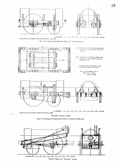
Page marked '19': This shows, at the top, a tracing of the original drawing in the records of the manufacturer. Below are plan and elevation of the 'PLANET' TYPE FRAME. The driving axle had six bearings - two on the outside frames and four on the inside frames. The diagram at the bottom of this page shows the 'Planet' motion. There were slip eccentrics to control the valve on each cylinder. By operating a foot treadle, the driver could set the eccentrics for forward or backward motion. This rather inconvenient arrangement has been described in 'Lionsheart [Reference 1]
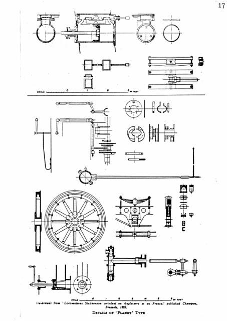
Page marked '17': This page has a feast of details. In this case, Warren drew on 'Locomotives Stephenson circulant en Angleterre et en France' by Champon, published in Brussels in 1835. At the top of the page is the detail of the cylinder, with the slide valves working horizontally above the cylinder. Immediately below are details of the valves, valve rod, slide bars and crosshead.
The two slip eccentrics are shown towards the middle of the page, together with the linkage from the foot treadle on the footplate which slides the eccentrics across the crank axle so as to engage in either the forward or backward position. Underneath is shown one of the two eccentric straps, hinged at its point of attachment to the eccentric rod. The vertical lifting link attached to the right of the eccentric rod is used to disengage the eccentric rod from the valve rod, allowing the valves to be set by hand for starting.
Lower down is the detail of a wheel, showing the bolted-on type. Next to the wheel are shown details of the axlebox and its method of attachment to the frames via the laminated spring.
The simple regulator valve is shown bottom left. This view can be usefully compared with a somewhat later type shown in 'Lionsheart' [Reference 5].
Finally, the crosshead-driven force pump used for the boiler feed is shown bottom right. Water at the bottom connection of the pumps is drawn into the chamber via the lower ball valve when the piston moves to the right. When the piston moves left, the lower ball valve closes and the upper ball valve is unseated, allowing the water out of the upper pump connection and into the boiler.
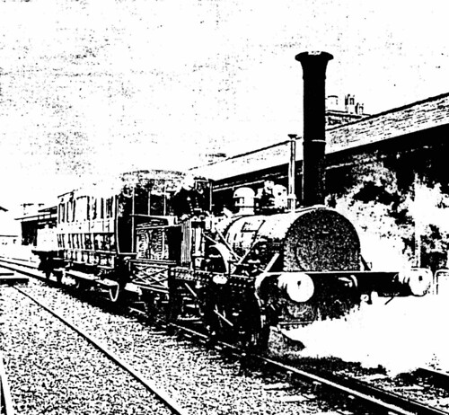
'Planet' class locomotives were exported. The ancient photograph below (from 'The Pictorial Encyclopedia of Railways' by Hamilton Ellis, published by Paul Hamlyn, 1968) shows the 'Pioneer' of the Bangor & Piscataquis Railroad, U.S.A., built by Robert Stephenson in 1836. This is possibly the only photograph ever taken of this type in service. The smokestack, whistle on the dome and bell were doubtless later American additions.
 'Pioneer' of the Bangor & Piscataquis Railroad, U.S.A., built by Robert Stephenson in 1836.
Adhesion is frequently the limiting factor on a locomotive. With a single driving axle, not all of the locomotive weight can be adhesive. In the case of the 'Northumbrian' class, there was about 4 tons on the driving axle. The 'Planet Class pushed this figure up to about 5 tons, with about 3 tons on the carrying axle. For freight and banking purposes, it was desirable to make all the weight adhesive. Thus a four-coupled version of 'Planet' appeared in 1831, starting with 'Samson' (which gave its name to the class) and 'Goliath'. More four-coupled locomotives followed. The drawing below shows the four-coupled 'Comet', produced in 1835 by Messrs. R & W. Hawthorn of Newcastle-upon-Tyne for the Newcastle and Carlisle Railway.
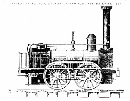 Passenger Engine, Newcastle and Carlisle Railway, 1835.
Any four-wheeled locomotive will have a rather uncertain gait when at speed and so it was logical that the effect of carrying wheels at the reat of the locomotive should be tried. In a single-driver, this produced a 2-2-2, in a four-coupled design, an 0-4-2 (like the 1838 'Lion'). The improved riding was very favourably received and greater design flexibility resulted as engines became larger and power increased. The iconic 'Patentee' class had been born. On some designs, the wheels on the centre axle lost their flanges to facilitate rounding curves but attention to correct end-play of wheel sets in the frames allowed designs which could negotiate curves whilst retaining flanges on all wheels.
The development of locomotive design has been dealt with by a host of authors. The works of Ahrons are best known but Clement Stretton's book [Reference 3] is also worth reading. However, this last author published the notorious drawing of 'Planet' in her supposed original condition, with a low-slung outside frame passing underneath the driving axlebox. Warren discounts this arrangement, believing it to stem from early proposals never implemented. Caution is needed in assessing the accuracy of different sources.
But, beyond any doubt, the 'Planet' class marks a very important phase in locomotive history and we welcome the Manchester replica as filling the slot between 'Rocket' and 'Lion'.
Notes
[Note 1] The Shaw Prints, together with the Ackermann Prints are two of the best sources of contemporary images of the Liverpool and Manchester in its early days. Photography was only just emerging from the experimental stage so artists produced drawings on site which were then turned into engravings which could be printed and sold to an interested public. The Shaw Prints in this article are taken from a splendid facsimile published in 1980 by Hugh Broadbent, Oldham, to celebrate 150 years of the Liverpool and Manchester.
[Note 2] 'Lionsheart' is the Occasional Newsletter of the Old Locomotive Committee, also called 'OLCO' the "Supporters' Club" for the 1838 locomotive 'Lion'. There are an number of posts about 'Lion' and 'OLCO' in this blog - you can find them all here. 'OLCO' also has its own website here.
References
[1] 'Valve Motions', LIONSHEART, May 1992.
[2] 'A Century of Locomotive building by Robert Stephenson & Co. 1823 - 1923' by J.G.H. Warren.
[3] 'The Development of the Locomotive - A Popular History 1803 - 1896 by Clement E. Stretton.
[4] 'Locomotive Engineering and the Mechanism of Railways A Treatise on the principles and construction of the locomotive engine, railway carriages and railway plant' by Zerah Colburn.
[5] 'LION The Questionable Origin of her Boiler', reprinted in LIONSHEART, September 1992.
Drawings and Pictures
'Planet'
Museum of Science and Industry (includes pictures of 'Planet').
Liverpool & Manchester 175th (includes pictures of 'Planet').
Liverpool & Manchester 180th (includes pictures of 'Planet').
'Planet' Drawings
Shaw: Views of the Liverpool & Manchester Railway
